 Circuit Breaker Dissection
Anyone ever wonder how a circuit breaker works? I dissected some and thought it was interesting to see how they work, and thought I'd share the pics and what I learned.
These ones that I dissected are an older style that is called "Zinsco" brand. First, the view of the breaker from the outside with it put together:

(I drilled out those rivets, by the way, to take it apart.)
Now, the inside views...
Switched on:

Switched off:

"Tripped" off (from too much current):
Here is some detail of the electrical contacts, which "make or break" the electrical circuit. The contacts themselves are little "pucks" of some alloy of silver (and possibly including tungsten.) Those silver alloy pucks are soldered (using a solder that has cadmium in it, I learned), to moving and stationary copper parts.

The motion of the moving parts of the circuit breaker, when it trips, is apparently designed to pull air into the circuit breaker, which gets directed through the nearby plastic "air baffles" and assists with "blowing out" any arc that is still happening between the contacts.
You can see views of breakers that have different amperages here (notice the color of the handle is different and indicates the breaker's amperage rating)


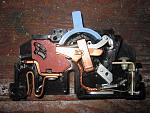
The only functional part that makes a breaker trip at a particular amperage (15 amp, 20 amp, 30 amp, etc.) is a bimetallic strip shown as the bent "L" shaped part here (sorry, it's out of focus, but it is welded to the multi-stranded braided copper wire, and also to the copper piece on the right side:

There were numbers stamped into the bimetallic that were different with the different circuit breaker amperage ratings. It has a nickel alloy that doesn't expand/contract with heat as much as the other side of the strip (which is a more conventional alloy), so the strip bends when it gets hot and trips the spring-loaded mechanism that opens the circuit.
It's a pretty complicated mechanism with multiple springs and moving parts. What's remarkable is how it manages to reset itself when the handle of the breaker is pressed back into the "on" position.
I believe there also may be some mechanism for a sudden current to trip the breaker with magnetic force, and I think that may be what the U-shaped piece of metal in the bottom of the above picture is for, but honestly I haven't got that completely figured out yet. But supposedly, these breakers can trip either from excessive sudden current (with likely some kind of electromagnet involved), or from excessive prolonged mild current (which would be from the heating up and the bending of the bimetallic strip.)
-------------------------------------
By the way, these Zinsco breakers have a bad rap (in the home inspection industry at least) for some of them using aluminum in the bus bars and the metal parts that grab the busbars, instead of copper. Although most of mine were copper, I did have a couple breakers (I don't think they were original breakers they were probably replacements) that had aluminum parts that grab the bus bars. The bus bars inside my breaker box were copper (tin plated), but I've heard some of them have aluminum bus bars.

There was one spot where the bus bar in mine had evidence of arcing (sooting and and pitting.)
Last edited by jakeru; 02-29-2012 at 05:41 PM.
'13 Everlast 255EXT
'07 Everlast Super200P


 Reply With Quote